To Route Raceway
The Raceway Router enables you to interactively route raceway in your current design file.
Before you start:
- Experience with 3D MicroStation environment and working knowledge of AccuDraw is a prerequisite for productive use of OpenPlant Modeler raceway placement tools. If you are not familiar with MicroStation 3D environment or not proficient with AccuDraw use in 3D model, please review available classes in Bentley learn before starting to use OpenPlant Modeler .
- Selection of RW catalogs is different in imperial and metric datasets. Make sure that your project is configured to use proper catalog selections (imperial or metric)
- Select Raceway Router from the Raceway ribbon.
- Click the Raceway configuration to display the Raceway Configuration drop down section.
- Click the Setup Grid button to configure the raceway layout.
- In the Setup Grid dialog, set the number of rows, columns and spacing for the layout.
- Click OK to return to the Raceway Routing Tool. The raceway layout displays a 3x2 grid.
- Alternative to using setup grid option was to manually add rows/columns and define spacing between them. To do this select row or column, make right click and select option Add from the context menu.
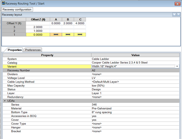
- Select the entire first row in the Raceway layout grid and click the Properties tab.
- Select Cable Ladder as the system value.
- Select a catalog from the list such as Cooper B Line Series 2,3,4 & 5 Steel.
-
Select a size such as 18" x 4".
Note: All other properties are optional and can be changed after the raceway is placed using the Raceways Properties tool.
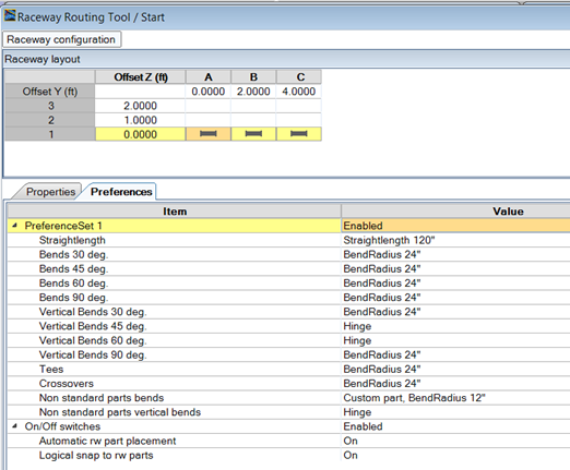
- Switch to Preferences tab. In this section preferences for RW bend radius can be configured. This is especially important if different raceway sizes are placed in a single configuration (larger raceway size typically requires larger bend radius).
- Select the remaining 2 rows and define different raceway type and sizes.
-
Optional: Once the raceway configuration is
complete it can be saved for future use. Type in configuration name then use
option
Save to save it. All users that are working on
the same project will be able to use this saved configuration.
-
Optional: The Preview can be used to preview
the raceway configuration before placement.
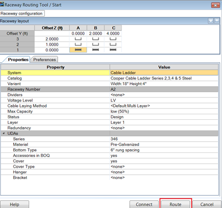
-
To start placing raceway, click
Route from the bottom of the Raceway Router
dialog.
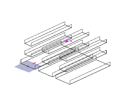
Insertion or placement point for entire raceway group is (Offset Y, Offset Z) = 0,0. In this case it is raceway in the lower left hand corner.
- To start raceway placement at correct elevation use snap and offset AccuDraw functions.
- For example, to place raceway 25 feet away from the existing raceway, make point of origin at the existing raceway and offset it for 25 feet in Y direction and 5 ft in Z direction.
- Click a data point to start the raceway placement. Notice that insertion point is lower left corner (or (0,0) offset defined in Raceway Router).
- Place a 50 ft long section using AccuDraw.
- To make a 90 degrees horizontal bend simply move cursor towards the bottom of the screen and place an additional 50 ft long section.
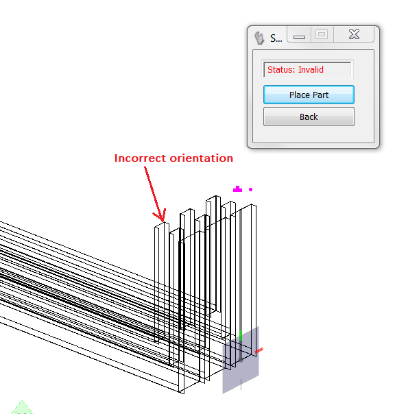
- To Place vertical bend change AccuDraw orientation to Front by typing F while Accudraw is in Focus. Notice that status is invalid because cable tray is not properly oriented. (The channels are facing outwards instead of inwards.)
-
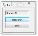
Type in
RY to rotate cable tray.
Once the RY option is pressed twice, the cable tray is properly rotated as shown below.
- Make a 10 ft long vertical section by typing 10 in AccuDraw.
- To go back to top rotation type in T while AccuDraw is active. Place additional 25 ft long straight section.
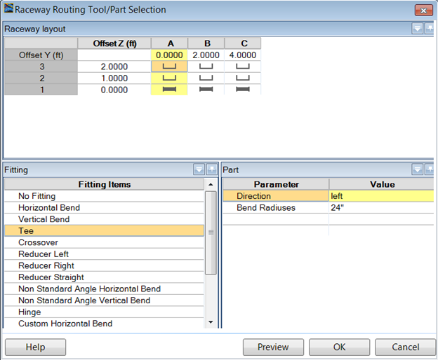
- The raceway configuration can be branched off from the main run or after the main run placement is complete. To branch off one section select Place Part.
- When the Raceway Routing Tool/Part Selection dialog opens up select the entire first row and set the following options:
- Select OK to place the tee.
- After Tee is placed continue placing additional 25 ft long section and finish placing it with data point.
- Right-click to complete the placement procedure.